Modeling
Author: Vincenzo Mossuto Creation Date: 30/09/2025
Last Reviewer: Sara Altomare/Rossana Mazza
What it is
This document describes all the scripts in the Modeling section included in the Spaarkly Scripts add-on for Blender:
- Create lens base
- Select sharp edges
- Add Standard X Mirror
- Setup FULL
- Set contact point
- Temples rotation angle
- Rotate temples
- Setup CUT
The Modeling section contains the scripts to be used during the different stages of the modeling process.
The first tools, such as Lens Base, Sharp Select, and Standard Mirror, are meant to support the actual modeling work by generating lens geometry, refining edge selections, and applying symmetry.
The final setup tools, on the other hand, represent the closing stage of modeling: they align and position the glasses correctly, either in their full version or in the cut version for VTO, making the model ready for export and the next steps of the pipeline.
See the Workflow – Modeling section for detailed guidelines and best practices.
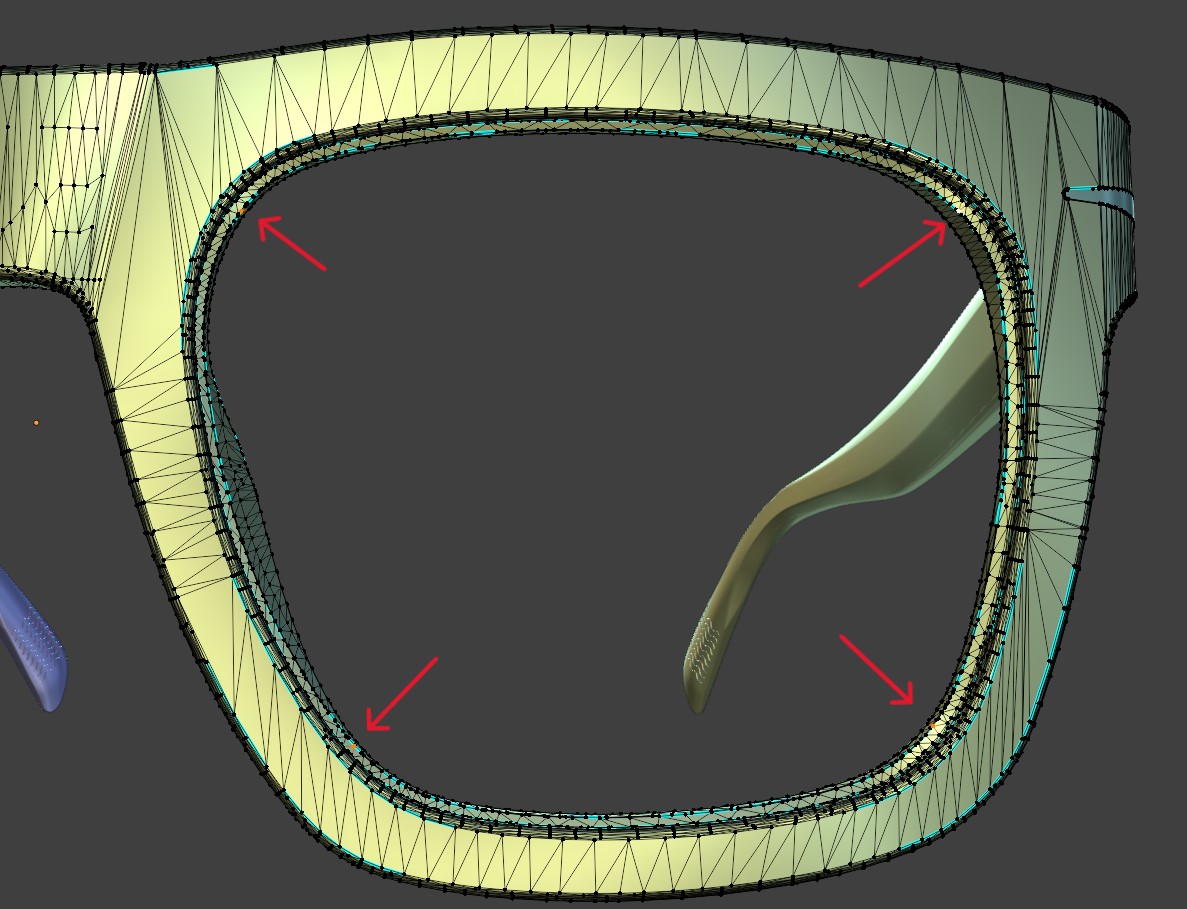
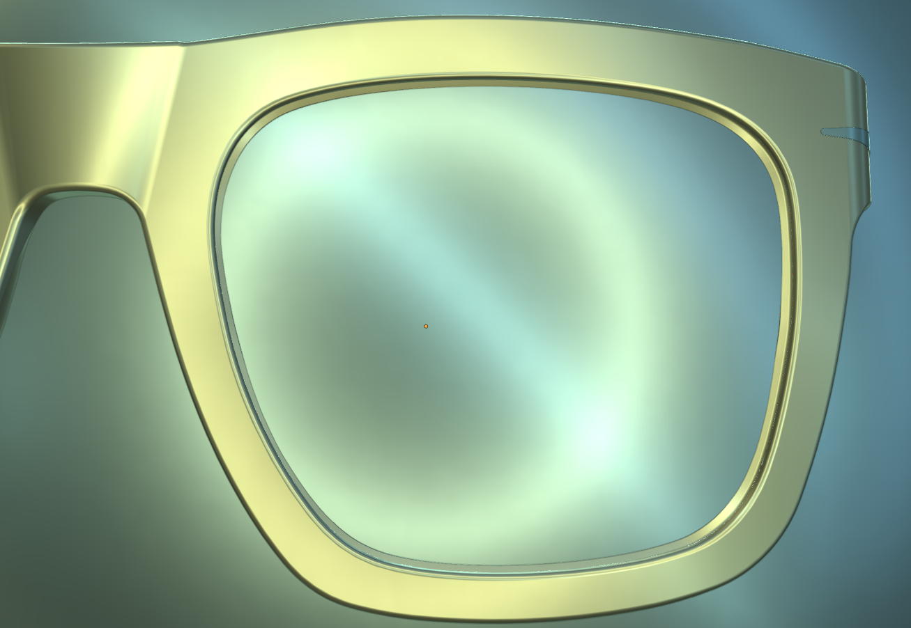
Create Lens Base
What it does
Creates a perfect UV sphere that passes through exactly four selected vertices of a mesh.
Useful to derive a lens base curvature or to prototype a new lens from scratch using reference points.
Prerequisite
- At least one object selected (the operator won’t run otherwise).
- A mesh object is active.
- In Edit Mode → Vertex Select, select exactly 4 vertices on the same object that define the desired lens curvature.
- The operator will automatically switch to Edit Mode if needed, but the 4 vertices must be selected on the active mesh.
Steps
1. Prepare the selection
Select your mesh, go to Edit Mode, and select 4 vertices that the sphere must pass through.
2. Run Create lens base
Spaarkly Scripts → Modeling → Create lens base
- The operator reads the world-space positions of the 4 selected vertices.
- If more than 4 vertices are selected → it cancels with
Selected more than 4 vertex. - If fewer than 4 vertices are selected → it cancels with
Selected less than 4 vertex.
3. Sphere fitting
The script solves a 3×3 linear system to compute the sphere center and radius that pass through the 4 points.
4. Sphere creation
It exits Edit Mode and adds a UV Sphere at the computed center, then scales it so the surface goes through all 4 points.
- Resolution:
segments = 256,ring_count = 128(high-quality surface). - Applies Scale and sets Shade Smooth (by angle).
5. Result
You get a new, separate lens base sphere placed and sized to match the selected vertices.
A status message confirms Center and Radius.
Troubleshooting
-
“Selected more than 4 vertex.” / “Selected less than 4 vertex.”
Make sure exactly 4 vertices are selected on the active mesh. -
No sphere created / operator cancels
Ensure a mesh is active and you are in Edit Mode with vertex selection. -
Math/precision issues (rare)
If the 4 vertices are coplanar or nearly degenerate, solving the system can fail (the matrix can’t be inverted).- Pick vertices that better describe a sphere (not all on the same plane or a straight line).
-
Performance
The UV sphere is very dense (256 × 128). If your scene is heavy, you can reduce segments/rings in the script for faster interactions. -
Transforms
The operator works in world space and applies scale to the created sphere. Existing transforms on your reference mesh are left untouched.
Select Sharp Edges
What it does
Selects all edges in the active mesh that are marked as sharp.
This is useful to quickly highlight edges that should remain crisp and for controlling normals without additional geometry.
Prerequisite
- At least one mesh object must be selected.
- The operator works in Edit Mode. If you are in Object Mode, it will automatically toggle to Edit Mode.
- A mesh must have edges already flagged as Sharp (
Ctrl+E → Mark Sharpin Blender).
Steps
-
Select the object
Pick a mesh object that contains sharp edges. -
Run Select sharp edges
Modeling → Select sharp edges- The operator automatically ensures you are in Edit Mode.
- It deselects everything and switches to Edge Select mode.
-
Sharp edge detection
The script scans all mesh edges and selects those whereedge.smooth == False(marked as sharp). -
Result
All sharp edges are now highlighted and can be used for further modeling actions (creasing, beveling, etc.).
Troubleshooting
-
Nothing is selected
Check that the mesh has edges explicitly marked as Sharp (Ctrl+E → Mark Sharp). -
Operator does nothing
Make sure the active object is a mesh and not another type (curve, light, etc.). -
Unexpected selection
If edges appear incorrectly marked, check Normals and reapply Clear Sharp/Mark Sharp to clean up edge data.
Add Standard X Mirror
What it does
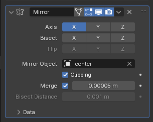
Adds a Mirror modifier to all selected objects.
If an object named “center” exists in the scene, it will be used automatically as the Mirror Object Center.
The modifier is preconfigured for symmetry on the X axis, with clipping enabled and a low merge threshold.
Prerequisite
- At least one object must be selected.
- Optionally, an Empty named center should be present if you want a consistent mirror reference across objects.
Steps
-
Select the object(s)
Choose one or more objects in the scene. -
Run Add Standard Mirror
Modeling → Add Standard Mirror -
Mirror modifier applied
- A Mirror modifier is created for each selected object.
- Symmetry is set to the X axis only.
- If the object center exists, it is assigned as the mirror object.
- Clipping is enabled and the merge threshold is set to
0.00005for precision.
-
Result
The selected objects now have a standardized mirror modifier ready for use.
Troubleshooting
-
No object selected
The operator will throw an error: “No object selected.” -
No mirror object assigned
If no center object exists in the scene, the modifier will still work but will use the object’s own origin as reference. -
Unexpected behavior
Make sure your objects have a correct origin placement and that the center empty is positioned where symmetry should occur.
Setup FULL
What it does
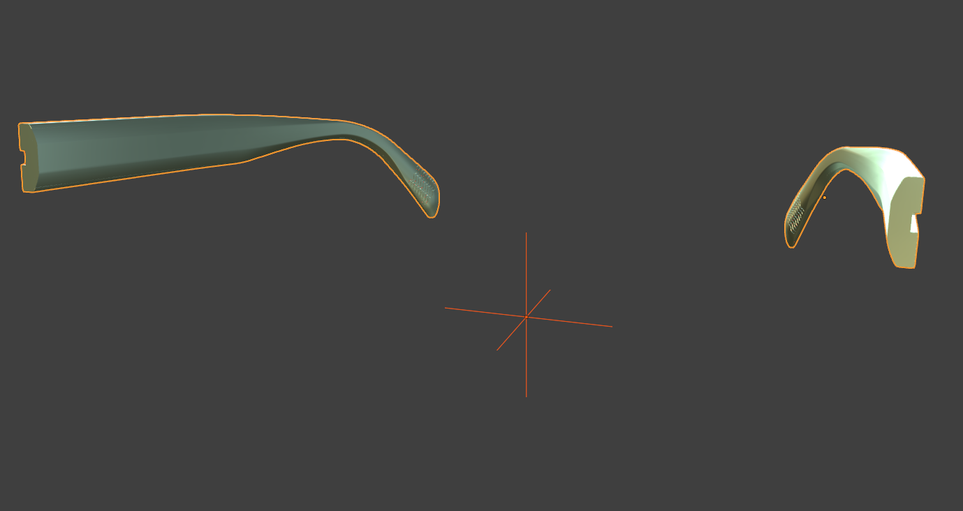
This operator is designed to automatically place the full version of the eyewear model in the correct position and orientation. By analyzing key reference points — such as the lowest vertices of the frame front and the temples or temple tips — the script aligns, rotates, and centers the model so that it sits properly on the ground plane.
Prerequisite
- Select all objects that belong to the model/collection you are exporting.
- The selection must include a mesh whose name starts with
FF(frame front). - The selection must also include either a mesh starting with
TT(temple tips) orTM(temples). - Objects must be mesh data; the operator samples vertices in Edit Mode.
Steps
-
Select all model objects
Make sure the selection contains at least oneFF_*and eitherTT_*orTM_*. -
Run Setup FULL
Spaarkly Scripts → Modeling → Setup FULL.
The operator switches to Object Mode, clears the console, and applies rotation & scale to the selection. -
Measure lowest Z on Frame Front
The script finds the lowest Z vertex on the activeFF_*object (by entering Edit Mode and scanning vertices in world space).If no
FF_*is found, it stops with: “The eyewear model is incomplete or the front has not been selected.” -
Measure lowest Z on back end (TT or TM)
It prefers aTT_*object; if none is found, it looks forTM_*.
The lowest Z vertex of that object becomes the back reference.If neither
TT_*norTM_*is present, it stops with: “The glasses appear to be incomplete or no terminal or temple has been selected.” -
Set cursor and pivot, compute tilt
- Sets pivot to 3D Cursor, and places the cursor at (X=0, Y=lowest_front.y, Z=lowest_front.z).
- Computes a tilt angle around X from the absolute differences between the front/back Z and Y values.
- Rotates the model about X by ± rot_angle so the glasses rest on the XY plane (based on which end is higher).
-
Measure lateral Y extents
- On
FF_*it records the lowest Y (stored ashighest_sidein code). - On
TT_*orTM_*it records the highest Y (stored aslowest_sidein code). - It then computes avg_y = (lowest_side.y + highest_side.y) / 2.
- On
-
Center in Y and snap to ground
Reselects all previously selected objects and translates by:- ΔY = −avg_y (centers the model on Y = 0)
- ΔZ = −lowest_front.z (drops the model so the front’s lowest Z sits at Z = 0)
-
Result
The glasses are centered, leveled, and grounded.
Troubleshooting
- “No object selected.” → Select the full model (all parts) before running.
- Front not found → Ensure at least one object is named with
FF_prefix. - Temple/Tip not found → Ensure there is a
TT_orTM_object in the selection. - “ERROR DURING TRANSLATION/MOVEMENT.” → The operator could not determine lateral references; verify the presence of valid
FF_*andTT_*/TM_*meshes. - Wrong orientation/centering → Check object prefixes and that the meshes actually contain vertices where expected (non-empty, correct geometry).
Set Contact Point
What it does
Sets the Frame Front (FF) object origin to a precise contact point for CUT/VTO workflows.
It supports two modes:
- Automatic (nosepads selected): If both nosepads
NP_SX_*andNP_DX_*are selected along with the FF, the script snaps the 3D cursor to their combined selection, applies a small offset (+0.005 Z, −0.004 Y) and sets the FF origin to that cursor. - Manual (vertex selection): If nosepads are not used, you can select one or more vertices (in Edit Mode) and the origin will be set to their median point.
Prerequisite
- At least one object selected.
- The selection must include a frame front object named with prefix
FF. - Optional: include both nosepads named
NP_SX_*andNP_DX_*for the automatic contact-point placement. - For the manual mode, you must be in Edit Mode with one or more vertices selected.
Steps
-
Select objects for your preferred mode
- Automatic: Select FF, NP_SX and NP_DX objects together.
- Manual: Select the FF object, enter Edit Mode, and select one or more vertices where the origin should be placed.
-
Set FF origin
Spaarkly Scripts → Final setup CUT → Set contact point -
Automatic mode (both nosepads selected)
- The script switches to Object Mode and sets origins to geometry for the current selection (median).
- It temporarily selects FF + NP_SX + NP_DX, snaps the cursor to the selection, applies the offset (+0.005 Z, −0.004 Y), then:
- Sets FF origin to the cursor.
- Restores your original selection.
-
Manual mode (Edit Mode vertex selection)
- You must be in Edit Mode; otherwise the script stops with an error.
- The script snaps the cursor to the selected vertices, switches to Object Mode, then sets the origin to the cursor.
-
Result
- The FF origin is now placed at the intended contact point (automatic via nosepads or manual via vertices), ready for CUT/VTO alignment.
Troubleshooting
-
“No object selected.”
Select the FF (and nosepads if using the automatic mode). -
“Frame Front not found.”
Ensure the front object is present and named withFFprefix. -
“Please select both of the nosepads.”
In automatic mode you must select bothNP_SX_*andNP_DX_*. Otherwise use the manual Edit Mode workflow. -
“Nosepad found but not renamed correctly.”
Rename nosepads to useNP_SX_*andNP_DX_*patterns. -
“You must be in Edit Mode to run this script.”
This appears if you’re using the manual vertex workflow but are not in Edit Mode.
Temples Rotation angle and Rotate temples
What it does
Opens the temples by a user-defined angle (from the Temple rotation slider) around each hinge screw.
The operator:
- Requires a Frame Front (
FF_*), both temples (TM_SX_*,TM_DX_*), and both hinge screws (SR_SX_*,SR_DX_*without numeric incrementals). - Applies rotation & scale, sets pivot to 3D Cursor, snaps the cursor to each screw, and rotates the corresponding temple (and related parts) around Z:
- Left side rotates outward by −angle,
- Right side rotates outward by +angle.
- Optionally includes side parts if present: temple tips (
TT_*), temple hinges (HN_*with_TH_), wirecores (WC_*), temple logos (LG_*), temple rivets (RV_*with_TR_), and temple decals (DC_*with_TT_, side-checked by X position).
Prerequisite
- Select the full glasses set you want to open.
- Selection must include:
FF_*(frame front),TM_SX_*andTM_DX_*(temples),SR_SX_*andSR_DX_*(hinge screws, no numeric suffixes like_01_).
- Name prefixes/suffixes must follow the Spaarkly convention (e.g.,
_SX_/_DX_,_TH_for temple hinges,_TR_for temple rivets). - Set the desired angle in Spaarkly Scripts → Final setup CUT → Temple rotation (degrees).
Steps
-
Select the model
Select the Frame Front, both temples, and both hinge screws (and any optional temple sub-parts). -
Set the opening angle
Use the Temple rotation slider to choose how much to open the temples (degrees). -
Run Rotate temples
Spaarkly Scripts → Final setup CUT → Set Temple Rotation.
The operator:- Applies rotation & scale, pivots to 3D Cursor,
- Left side: snaps cursor to
SR_SX_*, selectsTM_SX_*(+ optionalTT_,HN_with_TH_,WC_,LG_,RV_with_TR_,DC_with_TT_) and rotates −angle around Z, - Right side: snaps cursor to
SR_DX_*, selectsTM_DX_*(+ same optional parts on the right) and rotates +angle around Z, - Restores your original selection.
-
Result
Temples are opened symmetrically by the chosen angle, rotating around the hinge screws.
Troubleshooting
-
“No 'FF' object found in the selection.”
Ensure a Frame Front object (FF_*) is selected. -
“Both temples are missing.” / “Temple SX/DX not found.”
You must select bothTM_SX_*andTM_DX_*. -
“Both screws are missing.” / “Screw SX/DX not found.”
Screws must be present and not carry numeric incrementals (the operator ignoresSR_*_01_…etc.). -
“Left/Right temple rivet found but not renamed correctly.” / “Left hinge found but not renamed correctly.”
Check that temple rivets include_TR_and temple hinges include_TH_;_FH_(frame hinge) is ignored as a rotation target. -
Temple decals not rotating
Ensure temple decals useDC_*_TT_*and are on the correct side (the script side-checks by X position).
Setup CUT
What it does
Prepares the glasses CUT version for VTO export by recentring the model on the world origin using the Frame Front (FF_*) as reference, then (if available) adds a Boolean Difference with the object named cutter to the VTO-relevant parts (temples TM_*, temple tips TT_*, wirecores WC_*). It preserves transforms (applies rotation/scale first), ensures Object Mode, and finally moves the 3D cursor to (0, 0, 0) with pivot set to Cursor.
Prerequisite
- Select all objects that belong to the CUT/VTO collection you’re exporting.
- The selection must include a Frame Front object named with prefix
FF_. - (Optional but recommended) A scene object named
cutter. - Naming follows Spaarkly conventions:
TM_*,TT_*,WC_*for the parts that will receive the Boolean.
Steps
-
Select the CUT set
Select all components you intend to export for VTO (includingFF_*,TM_*,TT_*,WC_*, etc.). -
Run Setup CUT
Spaarkly Scripts → Final setup CUT → Setup CUT. -
Automatic recentering
The operator findsFF_*; translates the entire selection so the FF sits at (0, 0, 0); rotation & scale are applied beforehand. -
Apply cutter (if present)
If an object namedcutterexists, the operator adds a Boolean (Difference, FAST) to each ofTM_*,TT_*, andWC_*only if the same cutter isn’t already assigned. -
Finish
Pivot is set to Median Point during processing; the 3D cursor is set to (0,0,0) and Pivot → Cursor at the end.
Troubleshooting
-
“No 'FF' object found in the selection.”
Ensure the Frame Front is selected and correctly namedFF_*. -
“No cutter object found.”
Create/rename the cutter object tocutterif you need automatic Boolean trimming onTM_*,TT_*,WC_*. -
Boolean not applied
Verify that affected parts are namedTM_*,TT_*, orWC_*, and that a Boolean with object =cutterdoesn’t already exist on them. -
Model not centered as expected
The centering uses the object origin ofFF_*(not its geometry). ConfirmFF_*origin is correctly positioned (use Set FF Origin if needed).