Mirror Assembly
Disassembly
Important: follow the steps in the order shown to avoid damaging components. The monitor is fragile — always handle it with care.
Step 1 — Disconnect and remove the camera
Unplug the camera's USB-C cable from the back of the monitor. Remove the camera from the top edge of the screen. Always handle the camera by its base: do not touch the rotating parts or the lens. Place the camera back in its original box.
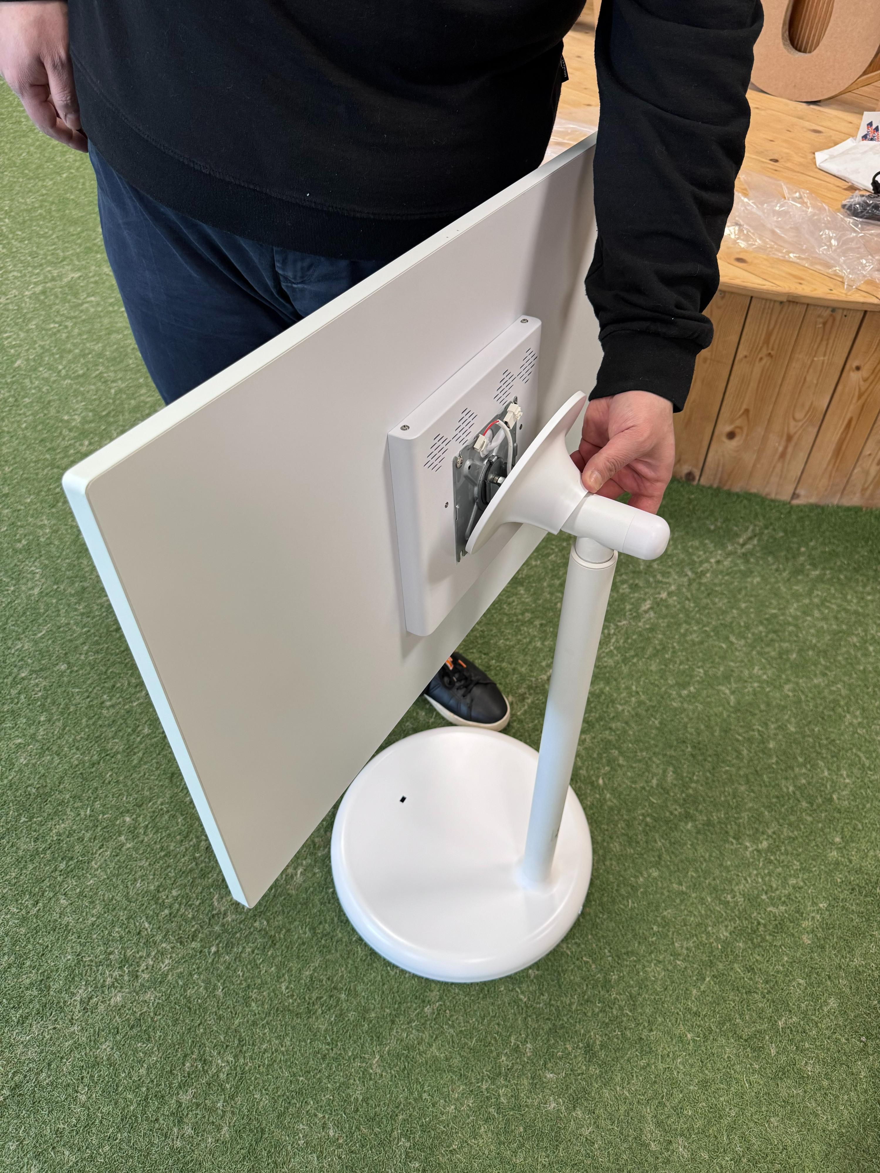
Step 2 — Rotate the monitor to landscape
Rotate the monitor from the vertical (portrait) position to landscape, keeping it perpendicular to the ground.
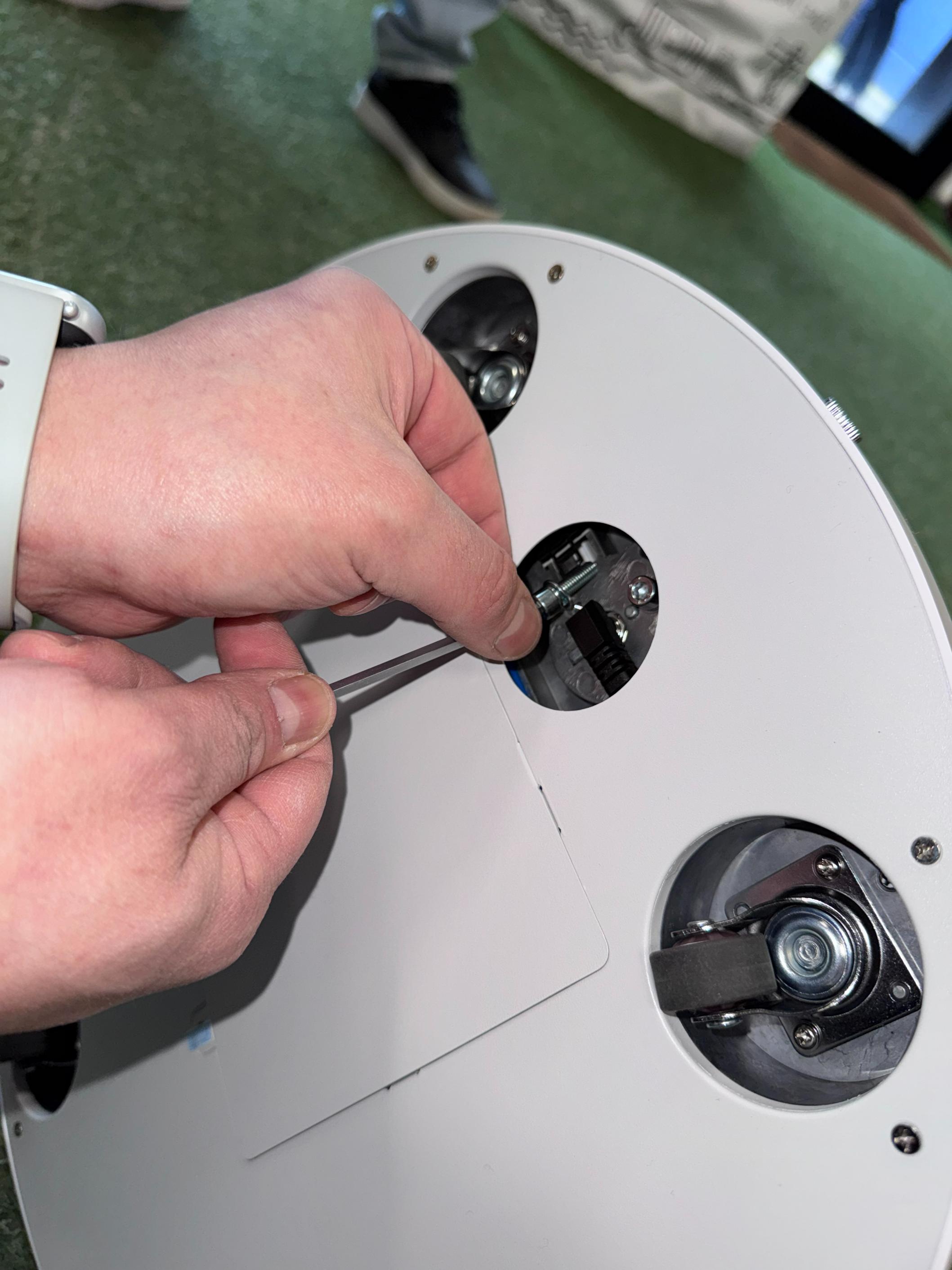
Step 3 — Lock the height adjustment mechanism
IMPORTANT: Lower the pole to its lowest position and tighten the locking screw at the bottom of the pole. This is essential to prevent accidental gas piston movement during transport.
Step 4 — Remove the magnetic cover
To access the monitor screws, remove the magnetic cover on the back. Unscrew it counter-clockwise, following the arrow printed on it.
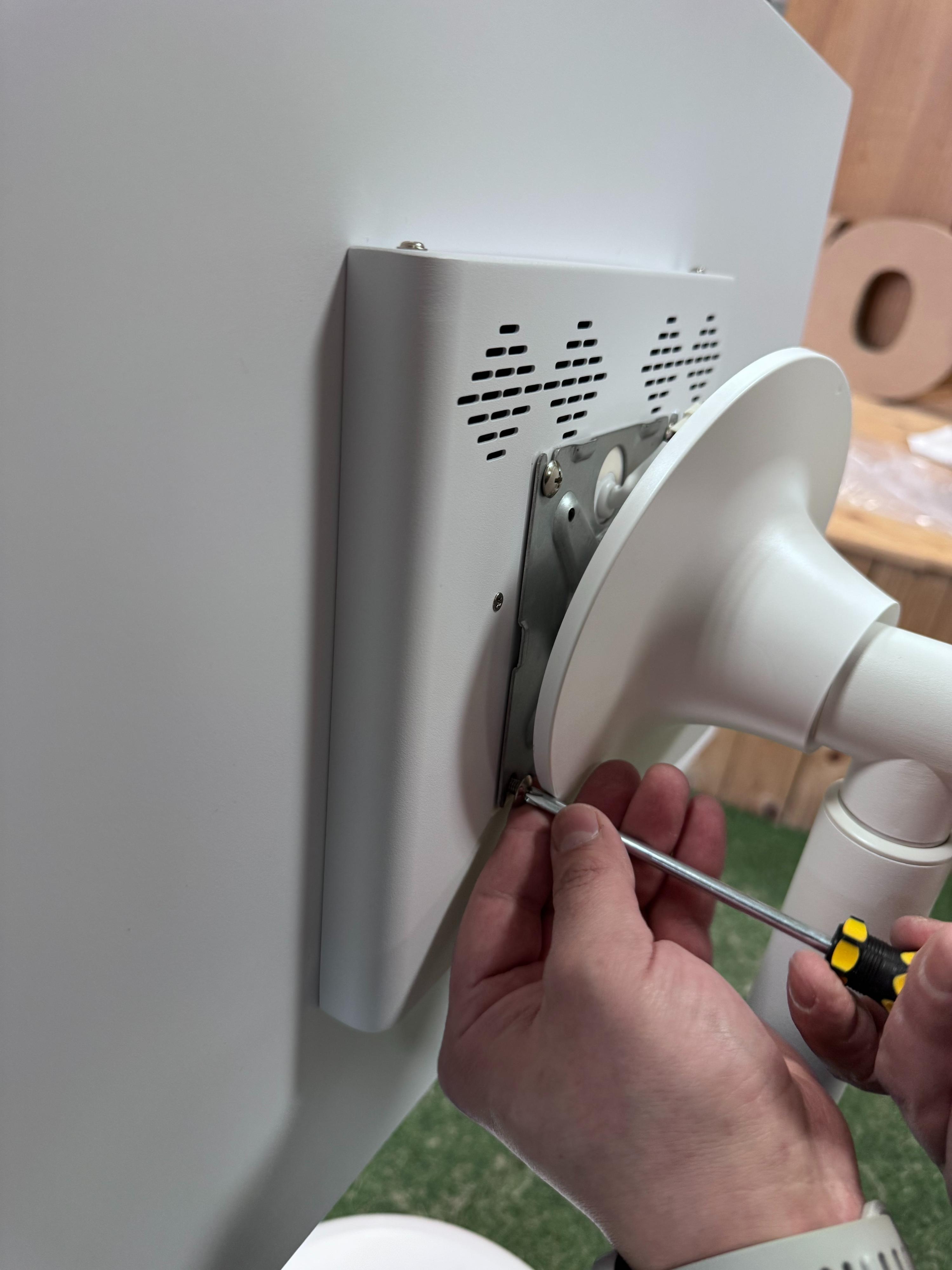
Step 5 — Remove the monitor screws
Using the screwdriver provided, slightly loosen the 2 top screws without removing them completely. Fully remove the 2 bottom screws.
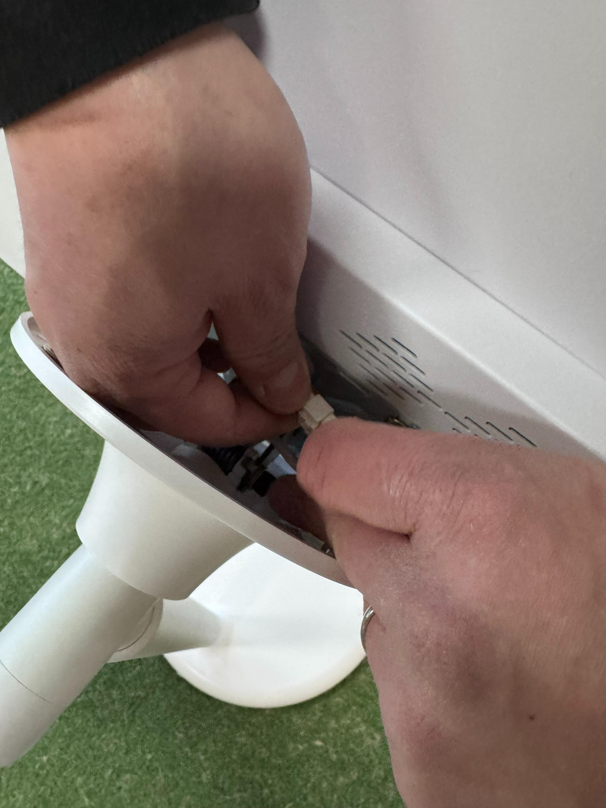
Step 6 — Disconnect the monitor power cable
Unplug the power cable from the port on the back of the monitor.
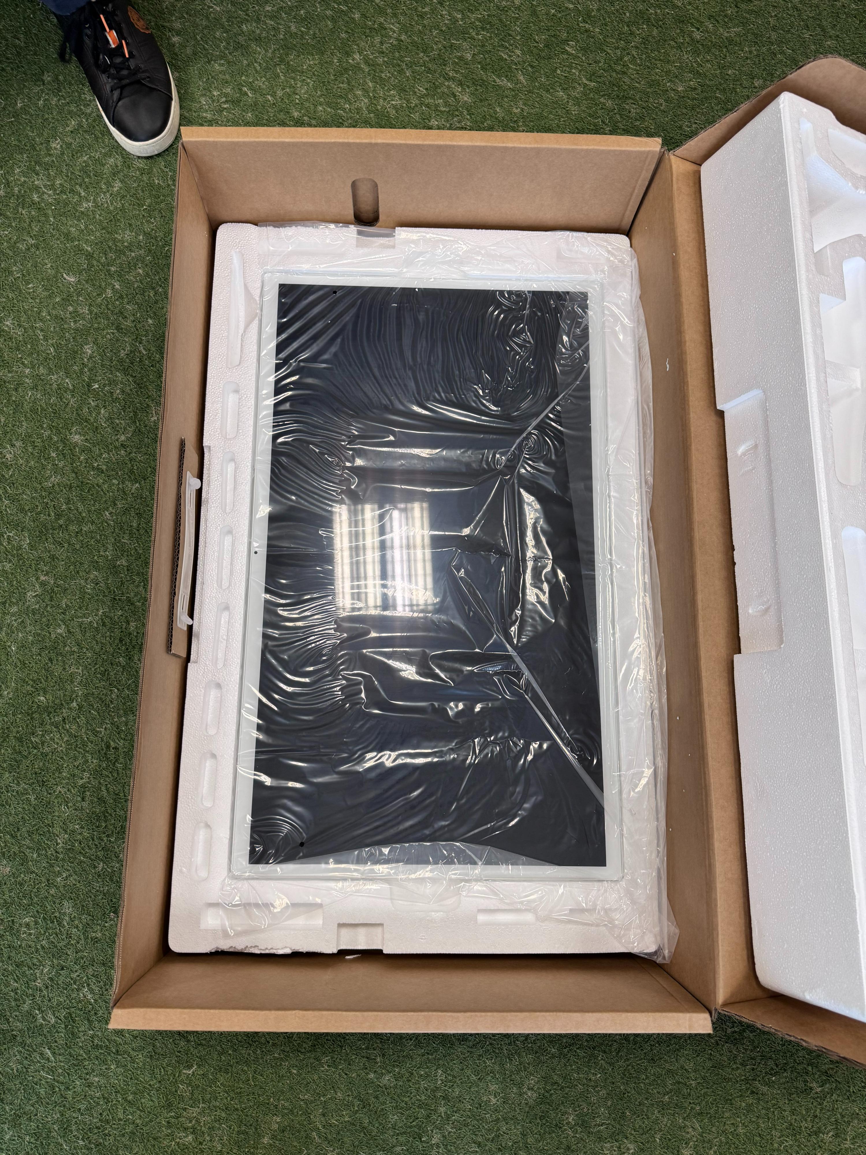
Step 7 — Remove and repack the monitor
Slide the monitor off the VESA mount rails. Carefully wrap it in the protective film and place it in the designated compartment inside the box.
Step 8 — Detach the pole from the base
Lay the base + pole assembly on its side. Using the Allen key, remove the 3 hex screws from the bottom of the base. Also disconnect the power cable from inside the base. Separate the pole from the base.
Step 9 — Repack the components
Place the pole and the base in their designated compartments inside the box with the original polystyrene.
Step 10 — Final check
After disassembly, verify that you have:
- 3 Phillips screws (monitor-to-VESA mount + pole locking screw)
- 4 hex screws (3 pole-to-base + 1 additional)
Keep all screws together with the accessory kit inside the package.